Barleywine time at HWTLO
Recently (thanks to the Internet), I figured out how to remote control a digital camera over USB using CHDK. However, if I wanted my MakerBot to be able to automatically control that camera, I needed a way to wire it up!
CHDK’s remote USB trigger functionality works by detecting when it receives power over USB. This happens when two wires inside the USB mini-B cable are connected to power: the red wire gets 5 volts, and the black wire gets connected to ground.
 So, I chose to find somewhere on the MakerBot’s electronics to hook up these power and ground wires such that the MakerBot could control when the red wire receives 5V. The MakerBot uses RepRap Generation 3 electronics, and let me tell you, the gen 3 electronics documentation is fantastic! Unfortunately, the docs for the main motherboard reveal that there are some free I2C headers for connecting serial devices, but no free general I/O pins.
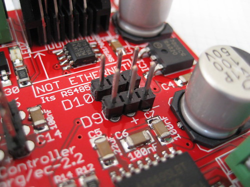
Luckily, the extruder controller docs show two free digital pins, conveniently broken out with 5V and ground connections next to them. These are digital pins D9 and D10. According to the docs, they are intended for hooking up servo motors, but they would absolutely work for my purposes!
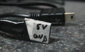 The layout for pins D9 and D10 goes (from left to right): I/O pin, 5V, ground. Since I wanted the data pin itself to provide the 5V, I chose to make a cable using a 3-pin piece of female header, soldering the red wire connecting to the I/O pin (on the left) and the black wire connecting to the ground pin (on the right). The center pin has no connection. You can see my “super fancy” cable on the left.
I know this post isn’t particularly about code, so stay tuned for the next parts of this series:
Throwing away the evening
 One problem with making time-lapse videos of MakerBot prints is the fact that the MakerBot works by moving the build platform (and therefore the object being built) around in the XY plane, resulting in an unwatchable blur.
It recently occurred to me that, since the MakerBot is such a hackable platform, I could probably make nice time-lapse videos by taking a picture of each layer. The idea is to have the MakerBot pose the object after each layer, and trigger a camera to take a snapshot.
When discussing this idea with fellow HackPittsburgh member Matt Mets, he recommended I try out a Canon camera with the Canon Hack Development Kit (CHDK). Making a quick stop on eBay, I soon had an SD300 in my hands, ready to be hacked!
I started by figuring out which firmware my SD300 was running, which told me which version of CHDK to download for my camera’s particular model/firmware combo. Using an SD card reader, I copied the contents of the CHDK zip file onto my camera’s SD card and followed the instructions to make CHDK auto-load when the camera starts up. I also changed my CHDK firmware settings to set “Disable LCD off” to “[Script]”, so the camera wouldn’t shut down on its own.
Once CHDK was loaded and configured, I followed the USB Remote Cable instructions from the CHDK wiki. The basic idea is to set Enable Remote to on, and load a script that is ready to handle USB remote events. The one on the wiki page didn’t work as-is for me, presumably because my camera has half-shoot (i.e. focus and charge flash) and full-shoot (take picture) settings. Here is the result that worked for me:
As the script says, I now turn the camera on in record mode, disable the flash, and start the script. After that, the camera will automatically take a photo whenever I plug in the USB to my computer.
More from this series: