Automatic MakerBot Camera Pt. 2 - Wiring it up!
Recently (thanks to the Internet), I figured out how to remote control a digital camera over USB using CHDK. However, if I wanted my MakerBot to be able to automatically control that camera, I needed a way to wire it up!
CHDK’s remote USB trigger functionality works by detecting when it receives power over USB. This happens when two wires inside the USB mini-B cable are connected to power: the red wire gets 5 volts, and the black wire gets connected to ground.
 So, I chose to find somewhere on the MakerBot’s electronics to hook up these power and ground wires such that the MakerBot could control when the red wire receives 5V. The MakerBot uses RepRap Generation 3 electronics, and let me tell you, the gen 3 electronics documentation is fantastic! Unfortunately, the docs for the main motherboard reveal that there are some free I2C headers for connecting serial devices, but no free general I/O pins.
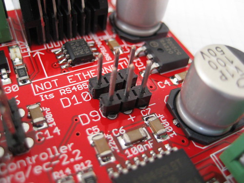
Luckily, the extruder controller docs show two free digital pins, conveniently broken out with 5V and ground connections next to them. These are digital pins D9 and D10. According to the docs, they are intended for hooking up servo motors, but they would absolutely work for my purposes!
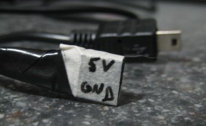 The layout for pins D9 and D10 goes (from left to right): I/O pin, 5V, ground. Since I wanted the data pin itself to provide the 5V, I chose to make a cable using a 3-pin piece of female header, soldering the red wire connecting to the I/O pin (on the left) and the black wire connecting to the ground pin (on the right). The center pin has no connection. You can see my “super fancy” cable on the left.
I know this post isn’t particularly about code, so stay tuned for the next parts of this series:
- Part 1: Remote control camera with CHDK
- Part 2: Wiring it up! [YOU ARE HERE]
- Part 3: Updating the MakerBot Firmware
- Part 4: Updating ReplicatorG
- Part 5: Updating Skeinforge
Comments
 Nathan
on
said:
Nathan
on
said:
That camera probably draws a lot of current from the USB power rails, especially if it can charge its battery from USB. How much current can those signal pins supply? It can't be much if they're directly connected to the I/O pins on the Atmel, which is what the doc suggests. You may have to stick a relay in there which gates power from a real USB port.
 Robert McGuire
on
said:
Robert McGuire
on
said:
You bring up a good point. Bizarrely, this camera doesn't charge via USB, it has a separate battery charger.
I haven't run it through an ammeter to see what it's actually pulling down but, spoiler alert, it seems to work with the 'bot just fine with short (~30-50ms) pulses. Time will tell if this fries my board! :)
 Matt Mets
on
said:
Matt Mets
on
said:
That camera is from back in the good old days before people really started to use USB to charge things.
Woo, looking great! Can't wait for the rest of the series :-)