This countertop is for dancing.
This countertop is for dancing.
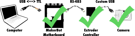
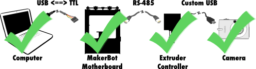
In the previous posts in this series, I hacked up a Canon camera to take pictures with an electronic trigger, built a cable to connect the camera to my MakerBot, and hacked the MakerBot’s firmware to enable it to trigger the camera in response to commands from the controlling computer.
The final step was to hack the desktop software that controls the MakerBot - ReplicatorG.
From the ReplicatorG website:
[ReplicatorG] is the software that will drive your CupCake CNC, RepRap machine, or generic CNC machine. You can give it a GCode or STL file to process, and it takes it from there. Its cross platform, easily installed, and is based on the familiar Arduino / Processing environments.
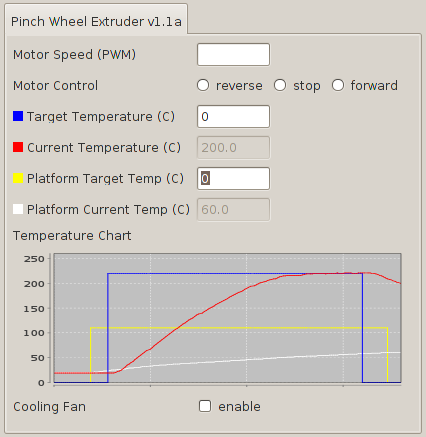
For my purposes, ReplicatorG provides two things. First, RepG is a user interface for controlling the MakerBot hardware:
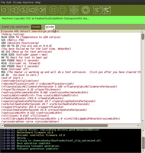
Second, RepG reads G-code files describing how to build an object, and transmits them to the MakerBot over the USB:
Of course, ReplicatorG is open source, and the code is available on GitHub! So, it was simple to clone their repository and start hacking on it myself.
While it was relatively simple to update the extruder controller firmware to make it camera-aware, ReplicatorG is a bit more complicated. My first goal was to hack a new “Camera” checkbox into the control panel. Whenever the box was checked, the camera would take pictures. Whenever the box was unchecked, the camera would be idle.
You can find the code required for these changes in this commit on GitHub, but I will try to briefly break them down here:
machines.xml.dist file, I defined an experimental MakerBot configuration named "EXPERIMENTAL - Cupcake CNC w/HBP and remote camera". It is essentially a copy of the typical MakerBot configuration with a heated build platform, but in the <tool> definition, I also added a camera="true" attribute.ToolModel.java, I added code to represent whether the tool has an attached camera, whether the camera is activated, and how to parse the camera attribute out of machines.xml.Driver.java, DriverBaseImplementation.java, and Sanguino3GDriver.java, I added the definitions and implementations to triggerCamera() and stopTriggeringCamera(). This is the code that actually sends the TOGGLE_CAMERA serial command to the extruder controller, which I also defined in ToolCommandCode.java.ExtruderPanel.java, I added the code to draw a new label and checkbox named "Camera", if the machine is configured for a camera, and to respond to check/uncheck events by calling triggerCamera() or stopTriggeringCamera().Compiling ReplicatorG is pretty simple, so long as you have a reasonable JDK environment and have Ant on your path. There are basically two steps:
machines.xml.dist to machines.xml`.dist-linux.sh, dist-mac.sh, or dist-windows.sh.ReplicatorG will be compiled and packaged up into the dist/ directory in two forms: an installable package for the chosen platform, and an unpacked version that you can run directly.
Opening up my modified version of ReplicatorG, I selected the “EXPERIMENTAL - Cupcake CNC w/HBP and remote camera” profile from the Machine -> Driver menu, opened up the control panel, and was happy to see this:
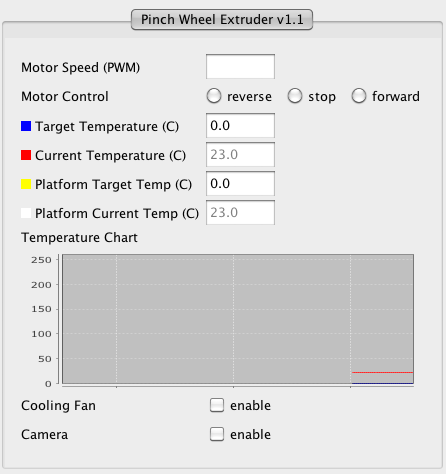
After hooking up my camera to the extruder controller’s D9 port, and starting the Remote Button script on the camera, I was able to take pictures by quickly toggling the camera checkbox on and off. I could also leave the checkbox activated to make the camera take pictures continuously.
Being able to trigger the camera by hand is all well and good, but my goal was to take pictures automatically at the end of every layer. To do this, I needed to be able to embed camera trigger commands in the G-code for building each individual object.
Looking at the ReplicatorG G-code docs, and the (machine-specific) M-code docs, I chose two codes for working with the camera:
M150 - Trigger CameraM151 - Stop Triggering CameraI may have to change these in the future, as the main ReplicatorG development team claim G- and M-codes for other features, but these work for now.
Modifying ReplicatorG to accept these M-codes (GitHub commit here) was straightforward: update GCodeParser.java to recognize the codes, and call the appropriate triggerCamera() and stopTriggeringCamera() methods.
I could now construct a G-code file which, when “built” in ReplicatorG, would take a picture on demand:
M150     (trigger the camera)
G4 P700  (wait 0.7 seconds for the camera to activate)
M151     (stop triggering)
G4 P1300 (wait 1.3 seconds for the camera to finish)
Finally, it was time to edit up the G-code for the models I want to photograph.
Typically, G-code is generated by taking a 3D object in STL format and running it through the Skeinforge tool. Skeinforge is a set of Python scripts, which means it is not too difficult to insert your own code.
For now, however, I decided to make a simple hack using a Perl script I wrote called add_camera_events.pl. It works by looking for (</layer>) comments, which signal the end of a layer of printing, and inserts lines to:
X=0, Y=-45),You can find the source for this script in the add_camera_events.pl gist. The source for all of my changes to ReplicatorG are on GitHub, in the “schmarty-camera” branch of my fork of ReplicatorG.
And with that, the computer aspect of this system was finally done!
Phew! So far I’ve hacked a camera, wired it to the MakerBot, updated the MakerBot firmware to trigger it, updated ReplicatorG to trigger it, and written a script to update G-code files with camera triggers at the end of each layer.
So… does it work? You bet! Stay tuned for more examples and a breakdown video of this whole project in the final post in this series!
In the previous post in this series, I figured out how to wire up my hacked Canon SD300 with CHDK. I chose to use the “D9” port on the Extruder controller board, thinking that should make the software as simple as setting pin 9 to “HIGH” for a brief time whenever I wanted to trigger the camera.
The next step was to update the software on the extruder controller so that it could activate (and deactivate) the camera, in response to commands from the motherboard.
The software for all three components is available on the indomitable GitHub. The software for your computer is called ReplicatorG, and the source can be found in the MakerBot ReplicatorG GitHub repository. I’ll talk more about ReplicatorG in the next post in this series. For now, we want to focus on the MakerBot G3Firmware GitHub repository, which contains the code for the motherboard (in the SanguinoMaster subdirectory), and for the extruder (in the ArduinoSlaveExtruder directory).
Browsing through the code, we see that these components use their serial interfaces to send packets, where each command is represented by a number. The commands for the motherboard can be found in the SanguinoMaster/Commands.h, and those for the extruder can be found in ArduinoSlaveExtruder/PacketProcessor.cpp.
To send a message to the extruder - in this case, to activate or deactivate the camera - we must create a packet for the motherboard. The HOST_CMD_TOOL_QUERY code allows us to send the motherboard a packet which it will then pass along to the extruder controller.
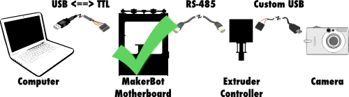
That’s great, because it means the motherboard part of this software hack is done!
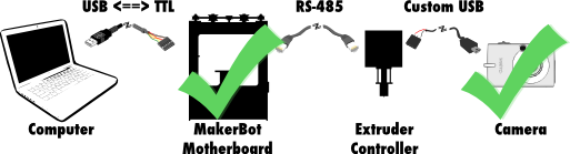
In fact, we’ve already hacked the camera, as well, so we’re halfway there!
To get this to work, I ended up changing the following files: ArduinoSlaveExtruder/Configuration.h.dist - added in configuration options for enabling the camera and setting the pin on which to activate it. ArduinoSlaveExtruder/Extruder.h - added function definitions for turning on/off the camera. ArduinoSlaveExtruder/Extruder.cpp - actually implemented turning on/off the camera. ArduinoSlaveExtruder/PacketProcessor.cpp - implemented the serial command to toggle camera.
ECv2.3rc0-camera branch.
To build the firmware and upload it to the extruder controller, we need some common development tools (make, in this case), and the Arduino development environment. With those things installed, we can compile everything by setting the ARDUINO_HOME environment variable to the path to our Arduino install’s java directory (e.g. on OS X this would be /Applications/Arduino.app/Contents/Resources/Java/), and simply run make.
Once the firmware has been compiled, we can upload it to the extruder controller by using the USB<->TTL cable that usually connects the motherboard to our computer. Plug the cable into the extruder controller, and run the make upload command. You’ll need to make sure that ARDUINO_HOME is set, and you will probably need to alter the Makefile to specify the correct serial port, and maybe to update the call to avrdude to include the path to the Arduino avrdude config file. You can see an example of that in this commit.
Once the firmware is uploaded to the extruder controller, the MakerBot is all set to take pictures!
… Of course, we still have no way to tell the MakerBot to take a picture, so stay tuned for that information in the next update:
It works!
Using a Canon SD300 with CHDK, and some firmware hacks, Makerbot #131 has learned how to make time-lapse videos of all of its prints!
More details (and a how-to!) coming soon! And thanks to Thingiverse user Starno for the bottle opener model in the video.
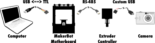
Recently (thanks to the Internet), I figured out how to remote control a digital camera over USB using CHDK. However, if I wanted my MakerBot to be able to automatically control that camera, I needed a way to wire it up!
CHDK’s remote USB trigger functionality works by detecting when it receives power over USB. This happens when two wires inside the USB mini-B cable are connected to power: the red wire gets 5 volts, and the black wire gets connected to ground.
 So, I chose to find somewhere on the MakerBot’s electronics to hook up these power and ground wires such that the MakerBot could control when the red wire receives 5V. The MakerBot uses RepRap Generation 3 electronics, and let me tell you, the gen 3 electronics documentation is fantastic! Unfortunately, the docs for the main motherboard reveal that there are some free I2C headers for connecting serial devices, but no free general I/O pins.
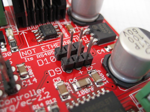
Luckily, the extruder controller docs show two free digital pins, conveniently broken out with 5V and ground connections next to them. These are digital pins D9 and D10. According to the docs, they are intended for hooking up servo motors, but they would absolutely work for my purposes!
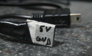 The layout for pins D9 and D10 goes (from left to right): I/O pin, 5V, ground. Since I wanted the data pin itself to provide the 5V, I chose to make a cable using a 3-pin piece of female header, soldering the red wire connecting to the I/O pin (on the left) and the black wire connecting to the ground pin (on the right). The center pin has no connection. You can see my “super fancy” cable on the left.
I know this post isn’t particularly about code, so stay tuned for the next parts of this series:
 One problem with making time-lapse videos of MakerBot prints is the fact that the MakerBot works by moving the build platform (and therefore the object being built) around in the XY plane, resulting in an unwatchable blur.
It recently occurred to me that, since the MakerBot is such a hackable platform, I could probably make nice time-lapse videos by taking a picture of each layer. The idea is to have the MakerBot pose the object after each layer, and trigger a camera to take a snapshot.
When discussing this idea with fellow HackPittsburgh member Matt Mets, he recommended I try out a Canon camera with the Canon Hack Development Kit (CHDK). Making a quick stop on eBay, I soon had an SD300 in my hands, ready to be hacked!
I started by figuring out which firmware my SD300 was running, which told me which version of CHDK to download for my camera’s particular model/firmware combo. Using an SD card reader, I copied the contents of the CHDK zip file onto my camera’s SD card and followed the instructions to make CHDK auto-load when the camera starts up. I also changed my CHDK firmware settings to set “Disable LCD off” to “[Script]”, so the camera wouldn’t shut down on its own.
Once CHDK was loaded and configured, I followed the USB Remote Cable instructions from the CHDK wiki. The basic idea is to set Enable Remote to on, and load a script that is ready to handle USB remote events. The one on the wiki page didn’t work as-is for me, presumably because my camera has half-shoot (i.e. focus and charge flash) and full-shoot (take picture) settings. Here is the result that worked for me:
As the script says, I now turn the camera on in record mode, disable the flash, and start the script. After that, the camera will automatically take a photo whenever I plug in the USB to my computer.
More from this series: