Automatic MakerBot Camera Pt. 3 – Updating the MakerBot Firmware
In the previous post in this series, I figured out how to wire up my hacked Canon SD300 with CHDK. I chose to use the “D9” port on the Extruder controller board, thinking that should make the software as simple as setting pin 9 to “HIGH” for a brief time whenever I wanted to trigger the camera.
The next step was to update the software on the extruder controller so that it could activate (and deactivate) the camera, in response to commands from the motherboard.
An aside on MakerBot communications
The MakerBot electronics ecosystem is comprised of 3 parts: your computer, the MakerBot's motherboard, and the extruder controller board. Your computer talks to the motherboard via a USB<->TTL interface (such as this FTDI cable from SparkFun). In turn, the motherboard communicates with the extruder using another serial protocol, RS-485, over an ethernet cable. Finally, the extruder triggers the camera via the custom cable I made in the previous post.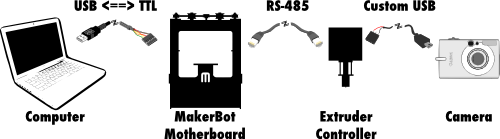
The software for all three components is available on the indomitable GitHub. The software for your computer is called ReplicatorG, and the source can be found in the MakerBot ReplicatorG GitHub repository. I’ll talk more about ReplicatorG in the next post in this series. For now, we want to focus on the MakerBot G3Firmware GitHub repository, which contains the code for the motherboard (in the SanguinoMaster subdirectory), and for the extruder (in the ArduinoSlaveExtruder directory).
Browsing through the code, we see that these components use their serial interfaces to send packets, where each command is represented by a number. The commands for the motherboard can be found in the SanguinoMaster/Commands.h, and those for the extruder can be found in ArduinoSlaveExtruder/PacketProcessor.cpp.
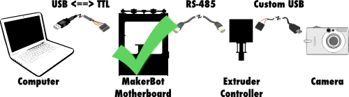
To send a message to the extruder - in this case, to activate or deactivate the camera - we must create a packet for the motherboard. The HOST_CMD_TOOL_QUERY code allows us to send the motherboard a packet which it will then pass along to the extruder controller.
That’s great, because it means the motherboard part of this software hack is done!
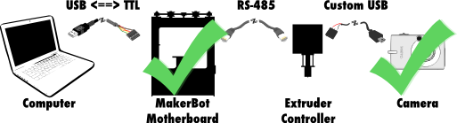
In fact, we’ve already hacked the camera, as well, so we’re halfway there!
Hacking a camera into the extruder controller
Since the motherboard already does everything we need (passes along packets from the computer to the extruder controller), we only need to update the ArduinoSlaveExtruder code.To get this to work, I ended up changing the following files: ArduinoSlaveExtruder/Configuration.h.dist - added in configuration options for enabling the camera and setting the pin on which to activate it. ArduinoSlaveExtruder/Extruder.h - added function definitions for turning on/off the camera. ArduinoSlaveExtruder/Extruder.cpp - actually implemented turning on/off the camera. ArduinoSlaveExtruder/PacketProcessor.cpp - implemented the serial command to toggle camera.
Building and uploading
If you followed the 4 links above, you'll notice that they go to my own G3Firmware GitHub repository. You can download it yourself to play along by cloning the repository and checking out theECv2.3rc0-camera branch.
To build the firmware and upload it to the extruder controller, we need some common development tools (make, in this case), and the Arduino development environment. With those things installed, we can compile everything by setting the ARDUINO_HOME environment variable to the path to our Arduino install’s java directory (e.g. on OS X this would be /Applications/Arduino.app/Contents/Resources/Java/), and simply run make.
Once the firmware has been compiled, we can upload it to the extruder controller by using the USB<->TTL cable that usually connects the motherboard to our computer. Plug the cable into the extruder controller, and run the make upload command. You’ll need to make sure that ARDUINO_HOME is set, and you will probably need to alter the Makefile to specify the correct serial port, and maybe to update the call to avrdude to include the path to the Arduino avrdude config file. You can see an example of that in this commit.
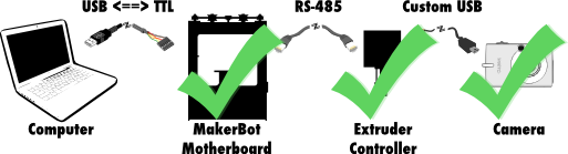
Once the firmware is uploaded to the extruder controller, the MakerBot is all set to take pictures!
… Of course, we still have no way to tell the MakerBot to take a picture, so stay tuned for that information in the next update:
- Part 1: Remote control camera with CHDK
- Part 2: Wiring it up!
- Part 3: Updating the MakerBot Firmware [YOU ARE HERE]
- Part 4: Updating ReplicatorG
- Part 5: Printing with the Camera!