Marty McGuire

Posts Tagged makerbot 131

2010
Sun Oct 24

Experiments with PLA 4043D

Bottle Opener made from PLA 4043D

As I said in my last update, I finally upgrade MakerBot #131 with a MK5 extruder because it reportedly works great with the new PLA 4043D.

I’ve been having fun printing with the various colors of ABS that MakerBot offers, but have always been somewhat envious of folks that have been printing successfully with PLA. I bought 5lb roll of the original 4032D that MakerBot sold, but ended up putting it on the shelf after reports from other operators that it was destroying their MK4 extruders.

Getting the new PLA printing was surprisingly easy, given the challenge of using a new extruder (which needed temperature, PID, and flow rate calibration) and it’s the first non-ABS plastic I’ve printed, so it will have different optimal printing temperatures and more.

I haven’t carefully calibrated the thermistor on my MK5, and I wasn’t sure of the right temperature to extrude PLA, so I started by setting the temperature to 180ºC and attempting to push some filament through by hand.  I raised the temperature slowly until it became easy to push through by hand, around 195ºC.  I had not yet locked down my PID settings, so I was getting some wild temperature swings.  To be safe, I set the temp to 200ºC and started printing my favorite bottle opener from Thingiverse.

It turns out the flow rate for the MK5 is a lot higher than it was for the MK4.  After putting down the raft, I was having trouble with the filament stripping inside the MK5 due to backpressure.  Still, by paying attention to the print and tightening the thumbwheel whenever the filament slipped, I was able to get a completed bottle opener.

It was then that I noticed two things:

  • The top two layers of the object sagged deep into the honeycomb fill layers below, giving a terrible finish on top.
  • PLA has no give, so there was no way that a penny would fit into the slot.  I have some nice bruises from trying to make it fit. :)
To fix the stripping and sagging problems, I figured that I should increase my Feedrate - the speed at which the platform moves to catch the extruded plastic.  I figured that a too-low Feedrate would cause some back pressure when printing the raft (leading to stripping), and would contribute to sagging overhangs.  I also guessed that the sagging is due in part to the high thermal mass of liquid PLA allowing it to sag before it cooled, so a lower extrusion temperature would let it solidify sooner, leading to less sagging.  I still use skeinforge-0006, so these settings are in "raft.csv" (various temperatures) and "speed.csv" (Feedrate), respectively.

So, some calibration prints:

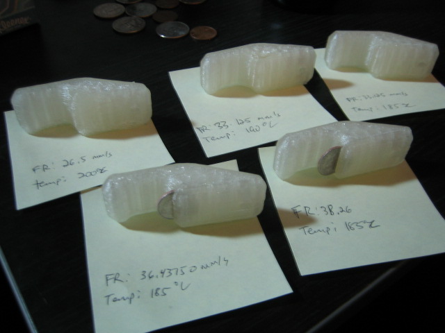
Bottle opener calibration prints with PLA

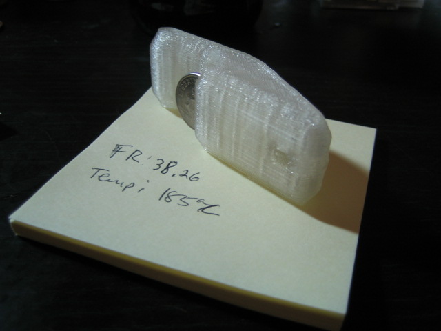
Starting with my first successful print in the upper-lefthand corner, with the temp of 200ºC and a feedrate of 26.5mm/s (which was working for my MK4), I slowly lowered my temp and increased feedrate.  At 180ºC I had a failed print due to the PLA freezing up, so I am going to stick with 185ºC going forward.  Increasing the feedrate by 25% immediately solved my filament stripping problem, but still left a pretty nasty top layer.  Increasing beyond that smoothed out the top pretty well, and left clean enough slots that I could actually insert some coins, albeit dimes rather than pennies.

I may try increasing my feedrate further, but I found an odd result when going from 36.4375mm/s (slower, should have thicker walls) to 38.26mm/s (faster, should have thinner walls). Namely, they both seem like very solid objects, but the dime slid nicely into the slower-printed version using the edge of a desk, while I had to take a hammer to the faster-printed version, and actually ended up bending the dime rather than driving it into the plastic (PLA is tough stuff!).  I would have expected the opposite.

Anyway, I hope these results are useful for some folks.  I hope to improve my calibration a bit more, and trying out the MK5 with my old roll of PLA 4032D.

MakerBot #131 Gets a MK5 Plastruder!

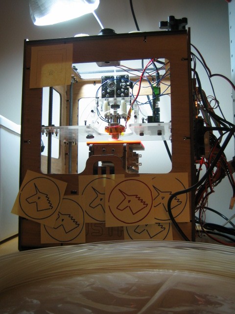
MakerBot 131 w/ MK5 extruder and PLA 4043D

Actually, all sorts of new and exciting nonsense has happened to MakerBot #131.

I was excited to order get my MK5 Plastruder kit and join all of the cool people who have left the pinch-wheel and nichrome behind.  Unfortunately, I ran into some problems early on, and after buying some cool thermocouple parts to try calibrating everything, finally determined that I had a bad thermistor.

So, I decided to put the MK5 aside and moved on to some entirely unrelated projects.  I assembled a Cyclops 3D scanner (I need more practice, but it’s promising!), and printed a pink, printable version of the Unicorn pen plotter (with some better-than-expected results - hence the Post-It Notes all over the ‘bot).  I had generally decided that the MK4 was Good Enough, and would come back to the MK5 when it died.

That was all, of course, before the new MakerBot PLA 4043D came out.  Once I got my hands on it, I had to go for the upgrade.  So, MakerBot #131 is now running the MK5, with the new relay board mounted with the official mounting kit, and the extruder controller mounted with donutman_2000’s awesome printable mount.

Stay tuned for details about my experience with the new PLA!  I am excited.

Sun Jun 13

MakerBot #131 Makes a Mendel!

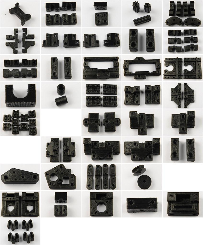
Image by Matt Mets

Like many MakerBot owners, I feel compelled to help spread desktop 3D printing throughout the world.  So, for the past several months, MakerBot #131 has been hard at work printing parts in 3D to make another 3D printer!

The Mendel is the second (and current) design for the RepRap project, whose goal is to create rapid-prototyping machines that can replicate themselves.  As an Open Source Hardware project, everything about the Mendel’s design is available online via Subversion, from the mechanical parts to the electronics schematics, to the source code for the device and its host machine.  Additionally, there is a fantastic community of very smart people who are constantly improving the design, trying new things, and helping others get their RepRaps working!

While the Mendel requires various hardware bits such as motors, electronics, nuts and bolts, etc., its structure is about 51% 3D-printed parts.  This works out to about 98 individual pieces that need to be printed, and represents a huge number of printing hours.

To get started, I used a .zip file full of the 3D STL files for these parts that someone very nicely prepared and uploaded to the MakerBot Operators group.  These files were from the 1.0 release of Mendel, so some of them ended up being out of date, and a few had issues that made them unprintable.  Thankfully, another kind MakerBot operator uploaded a fully prepared set to Thingiverse, so I could go there for a replacement whenever I found a part that wouldn’t print.

I started printing Mendel parts almost as soon as I got MakerBot #131 working.  Since I knew it was going to be a long process, I created a spreadsheet to help me track and estimate the time it would take to complete the build.  I also used some silly Javascript magic to display a progress bar on my MakerBot #131 page based on this spreadsheet data:

This hack was accomplished by building my own JSONP into some cells of the spreadsheet, and loading this content as Javascript using Google Spreadsheet's plain text export capability.  The spreadsheet cells were set up like this:

Here, column N47 contains the "completeness" of the Mendel as a value of 0.0 - 1.0 in terms of number of hours printed so far divided by the expected number of hours total.  This data could be used on an HTML page with an "update_mendel_progress" function by loading it with a script tag:

<script src="http://spreadsheets.google.com/pub?key=t7SNwhng2GkZjKWwwSOl2VA&single=true&gid=0&range=B52:E52&output=txt"></script>

The range "B52:E52" are the cells in my spreadsheet containing the JSONP call, and the "output=txt" option returns the data as tab-separated data, which Javascript is happy to parse.  The update_mendel_progress method on that page parses the number that is passed in, looks for an HTML DIV element with an id of "mendel_progress", updates it to be the appropriate width, and displays the percentage completion.

At any rate, after a lot of tweaking, many hair-raising moments, a required upgrade with the MakerBot Heated Build Platform v2.0, and hours and hours of printing, the parts were finally complete!  I gave them to Matt Mets, a member of HackPittsburgh, and you can see the photos he took of the parts, above!

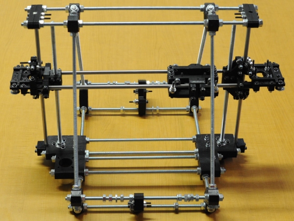
Despite some of the parts belonging to a slightly out-of-date design, Matt has been making progress on getting everything together!

You can follow Matt's progress on his blog.

I'm very happy to have finished off such a large project with MakerBot #131, and I have a lot of plans for it in the future, so be sure to watch this space for more updates!

Tue Feb 16

Automatic MakerBot Camera Pt. 2 - Wiring it up!

Recently (thanks to the Internet), I figured out how to remote control a digital camera over USB using CHDK. However, if I wanted my MakerBot to be able to automatically control that camera, I needed a way to wire it up!

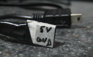
CHDK’s remote USB trigger functionality works by detecting when it receives power over USB.  This happens when two wires inside the USB mini-B cable are connected to power: the red wire gets 5 volts, and the black wire gets connected to ground.

So, I chose to find somewhere on the MakerBot’s electronics to hook up these power and ground wires such that the MakerBot could control when the red wire receives 5V.  The MakerBot uses RepRap Generation 3 electronics, and let me tell you, the gen 3 electronics documentation is fantastic!  Unfortunately, the docs for the main motherboard reveal that there are some free I2C headers for connecting serial devices, but no free general I/O pins.

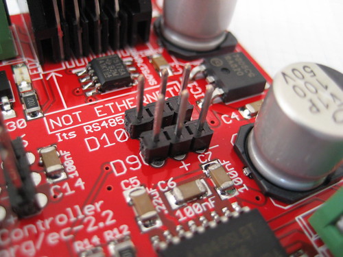
Luckily, the extruder controller docs show two free digital pins, conveniently broken out with 5V and ground connections next to them.  These are digital pins D9 and D10.  According to the docs, they are intended for hooking up servo motors, but they would absolutely work for my purposes!

The layout for pins D9 and D10 goes (from left to right): I/O pin, 5V, ground.  Since I wanted the data pin itself to provide the 5V, I chose to make a cable using a 3-pin piece of female header, soldering the red wire connecting to the I/O pin (on the left) and the black wire connecting to the ground pin (on the right).  The center pin has no connection.  You can see my “super fancy” cable on the left.

I know this post isn’t particularly about code, so stay tuned for the next parts of this series:

Mon Feb 1

Automatic MakerBot Camera Pt. 1 - Remote control camera with CHDK

One problem with making time-lapse videos of MakerBot prints is the fact that the MakerBot works by moving the build platform (and therefore the object being built) around in the XY plane, resulting in an unwatchable blur.

It recently occurred to me that, since the MakerBot is such a hackable platform, I could probably make nice time-lapse videos by taking a picture of each layer.  The idea is to have the MakerBot pose the object after each layer, and trigger a camera to take a snapshot.

When discussing this idea with fellow HackPittsburgh member Matt Mets, he recommended I try out a Canon camera with the Canon Hack Development Kit (CHDK).  Making a quick stop on eBay, I soon had an SD300 in my hands, ready to be hacked!

I started by figuring out which firmware my SD300 was running, which told me which version of CHDK to download for my camera’s particular model/firmware combo.  Using an SD card reader, I copied the contents of the CHDK zip file onto my camera’s SD card and followed the instructions to make CHDK auto-load when the camera starts up.  I also changed my CHDK firmware settings to set “Disable LCD off” to “[Script]”, so the camera wouldn’t shut down on its own.

Once CHDK was loaded and configured, I followed the USB Remote Cable instructions from the CHDK wiki.  The basic idea is to set Enable Remote to on, and load a script that is ready to handle USB remote events.  The one on the wiki page didn’t work as-is for me, presumably because my camera has half-shoot (i.e. focus and charge flash) and full-shoot (take picture) settings.  Here is the result that worked for me:

As the script says, I now turn the camera on in record mode, disable the flash, and start the script.  After that, the camera will automatically take a photo whenever I plug in the USB to my computer.

More from this series: